Coordination Drawing on BIM
Coordination drawings are mainly developed for sheet metal contractors, electrical contractors, mechanical contractors, and mechanical engineering consultants.
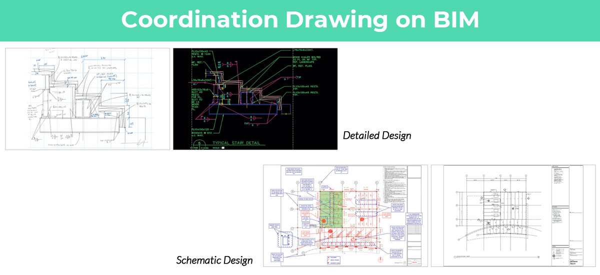
BIM generates the coordination process that takes individual 3D trade, architectural, and structural drawings to construct one comprehensive model integrating all trade models for the project. Later on a clash report will be created identifying all the clashes and conflicts between trade systems through a process of computerized collision checking and reporting until all trades are fully coordinated.
Once the design team resolve all spatial conflicts and the structural, architectural, MEP, and Civil systems are entirely coordinated, each consultant will give detailed coordination drawings of their respective systems fully annotated with dimensions (to column lines, to steel, elevations, etc) for submission to the Architect / Engineer of Record for review and approval. The fully coordinated model will be treated as reference model and be reviewed by the project team to coordinate compliance of fabrication models with design intention. Then these models shall be updated in a well-timed manner to reproduce design changes in the field.
Accurate coordinated drawings facilitate the construction team to get rid of RFI's, rework and wastages and create well-organized construction planning.
Steel fabricators and mechanical contractors have been utilizing BIM effectively for directly linking coordination drawings to fabrication processes.